Welcome to Logos Red, I go by logos and:
Want to hack a car?
In this post, we will build an OBD2 device that allows us to send remote commands to a car over Wi-Fi. I will cover everything from the tools and hardware you need to the software you will install.
We will build it using an ESP32 and a CAN transceiver board and install the ESP32RET software to integrate it with SavvyCAN.
Don’t worry, I made it as simple as possible with as many diagrams as I could. Anyone can follow along.
Disclaimer: Car hacking can have serious legal and ethical implications. Always ensure you have permission to work on any vehicle and use your skills responsibly.
My Promise
This post will finally end your meaningless search for a valid answer, and you will leave with a car hacking device.
If there are still any questions left, let me know so I can add it to help the next person who will arrive here.
My Goal
To help you improve in less time than it took me and to make sure you leave with what I promised.
I want you to join our community and for this to be a place that you revisit often.
- My Promise
- My Goal
- What we'll be covering
- Knowledge Requirements
- Introduction: Why build this device?
- Setting Up a Virtual Car Hacking Environment
- What tools do we need?
- Does our car have a CAN bus?
- PRECAUTIONS
- What hardware do we need?
- How to wire the components?
- Initial Testing Software
- Common issues
- Installing ESP32RET
- Conclusion
- More Resources
What we’ll be covering
- What tools and hardware we need to build our device.
- How to wire the device and set up the software.
- Connecting the device to our car to receive and send our first commands.
Knowledge Requirements
- An understanding of the CAN bus: Here is a guide from me explaining it
Introduction: Why build this device?
With this device, you can potentially unlock doors, engage the brakes, steer the car, anything a car does—depending on the vehicle’s security and CAN implementation. Along with being able to interact with a car’s ECU to reset, flash or dump firmware.
This project is an educational exercise designed to help you understand the CAN bus. By building this device, you’ll gain hands-on experience in sending remote commands to a vehicle, simulating what could happen if you were to hijack a CAN bus.
If you’ve ever seen the famous video of Charlie Miller and Chris Valasek hacking a Jeep, they hijacked the CAN bus to send commands:Here is a link to the video
They did that by exploiting a vulnerability in an open network port on the car. This allowed them to flash custom firmware and eventually access the CAN bus over GSM.
We’ll skip the exploitation part. Instead, we’ll connect the device directly to the OBD2 port to send commands over Wi-Fi.
All for less than $20.
Setting Up a Virtual Car Hacking Environment
While waiting for your hardware and tools to arrive now is the best time to practice your skills by hacking a virtual car:
Here is a post from me detailing exactly how to do that
What tools do we need?
You might not need to buy any tools. Depending on the hardware you buy, your header pins might already be soldered to the board. If you want to stick under $20 you can skip to the tools section, but I advise you to at least get a multimeter.
For comfort and clarity, I recommend these tools and accessories. They are in order of priority. You can click on each tool and see the one I recommend (No, they’re not affiliate links; buy from wherever you want).
- A multimeter: I would advise you to get one. It will help you troubleshoot bad connections, check voltages in your car, and see if components work.
- A soldering iron: Most boards you buy will lack header pins. You’ll have to solder them on. Don’t worry, soldering isn’t that hard, and an iron is cheap.
- Soldering wire: To solder, you will need some soldering wire. I recommend 0.7 – 1 mm, flux core, unleaded. Here is a video from Veritasium to convince you about lead.
- Flux: If you buy soldering wire with a flux core, you might get away without this. But I still recommend it. It helps the solder stick better to surfaces and makes your job easier.
- Helping Hands: No, I’m not talking about another human. I’m talking about a tool that holds your hardware while you solder. This tool, for me, is a must-have, but really it’s about comfort.
You can usually get all these inside a cheap toolkit, which should get the job done. As a beginner, they’re decent enough.
Does our car have a CAN bus?
The CAN bus was released in 1986 and mandated in the 2000s. So, if your car is made after the year 2000, it likely has CAN.
To check you will need a multimeter and access to the OBD2 port. There is this amazing website that shows you exactly where your OBD2 port is located: https://www.klavkarr.com/location-plug-connector-obd
Once you have located it, do the following:
- With your multimeter probe on ground, check the voltage on either CAN High or CAN Low. You should see a reading of 2.5 V or around that area.
Signal Ground is recommended (the one on the right, number 5) but chassis ground should work fine as well.
This does not guarantee that you’ll be able to hijack the CAN bus as there are gateways that might stop you. Or, your car might have different CAN implementations or other communication protocols.
PRECAUTIONS
- I recommend you get an extra Arduino Uno or get two ESP32s so you can test them out before you connect them to your car.
- The CAN bus is sturdy and it can handle even a short of 12V; click here for a really amazing video showing that off. All credits to Mechanic Mindset, he has some really good videos on the CAN bus.
- It’s unlikely you’ll damage the ECUs. Unplugging the battery should fix any faults. But there are possibilities of doing so.
- I’ll show you how to create your own makeshift CAN bus with two devices to test that everything is working fine before connecting them to your car.
- Make sure that when you’re working on the car, you keep your battery either trickle charging or turn the engine on every now and then. Else, you’ll end up with a dead battery.
What hardware do we need?
As I’ve mentioned in my CAN bus guide, an ECU is made up of 3 main components:
- Microcontroller
- CAN controller
- CAN transceiver
Other tutorials fail to mention that fundamentally we’re building our own simple ECU. We will connect it to the CAN bus via the OBD2 port to send commands.
So we need to buy those exact 3 parts: a microcontroller, a CAN controller, and a CAN transceiver.
Microcontroller
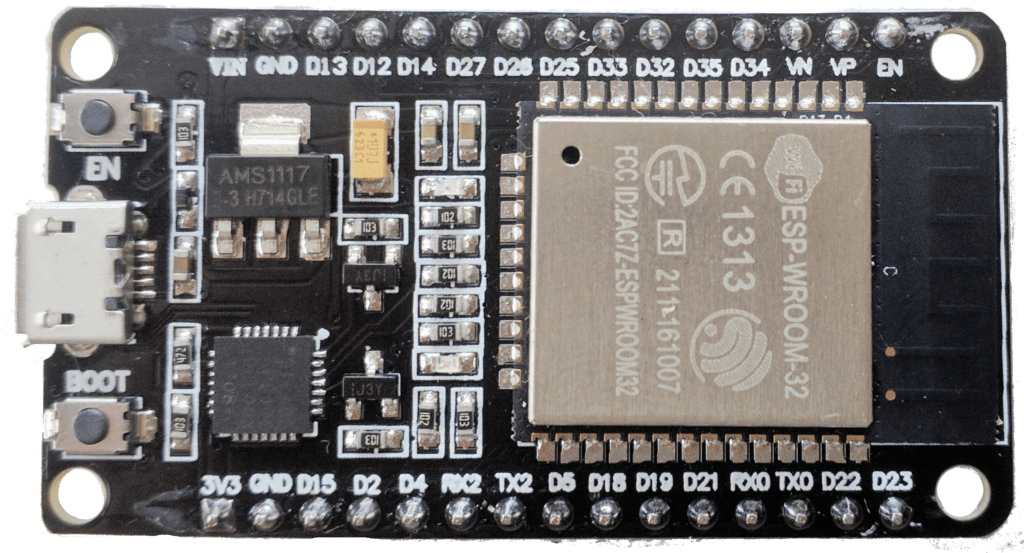
For my main board, I’ll be going with an ESP32-based board. There are a lot of versions of this board, but the one you are looking for is the Devkit V1. There are compatibility issues with other boards like the S3 that I can’t guarantee.
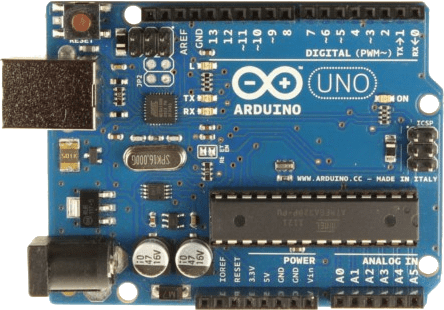
I’d also recommend you get an Arduino Uno so you can test both of the boards. In that way, you can make your own makeshift CAN bus.
Remember, these boards are open-source and anybody can make them. There are no counterfeits; you’ll find different designs from different manufacturers, buy whichever. The quality might differ but they usually all get the job done.
Here is a link to some ESP32 boards
Here is a link to some Arduino Unos
CAN Controller
If you’re using an ESP32 and not an Arduino board, the ESP32 already has a built-in CAN controller. There’s no need to buy an external one.
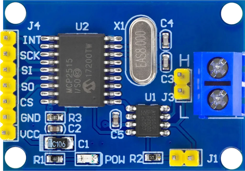
If you’re also buying an Arduino Uno, you need to get an MCP2515 board, which contains a CAN controller and CAN transceiver. So you can skip the CAN transceiver on the Arduino Uno side.
Here is a link to the MCP2515 (These are quite expensive on Amazon, usually they’re around $2)
CAN Transceiver
Here you have multiple options, they all achieve the same goal. But there is a big caveat that many other tutorials overlook:
The I/O pins on the ESP32 are rated for 3.3V, not for 5V.
- SN65HVD230: It’s what I’ll be using; you can find versions with the pins soldered on, but it depends. It operates at 3.3V; keep that in mind.
- TJA1050: What I bought originally before realizing that it operates at 5V. They’re fine, but you will need to buy a logic level converter board.
- MCP2551: Same issue as the TJA1050, operates at 5V and you’ll need to buy a logic level converter.
What is a logic level converter?
It simply converts the voltage from 3.3V to 5V and vice versa. It converts what each component interprets as 1s and 0s (logic levels), so they are on the same page.
I recommend you get a SN65HVD230, but if you can’t find any in your country, you should buy a TJA1050 or an MCP2551. Then you need to connect a logic level converter between the RX and TX pins; it’s not a big issue.
You can connect the transceivers directly and the board might work fine but you are slowly causing damage to it. It’s made to handle 3.3V not 5V.
Dupont wires
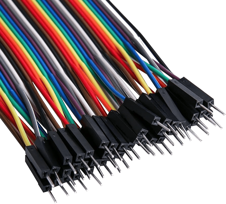
That’s the official name for the colored wires you see in projects. This is what we’ll be using to connect the hardware pieces together for testing. But I recommend you also buy prototyping wires and solder them directly for the final project.
Optional Hardware
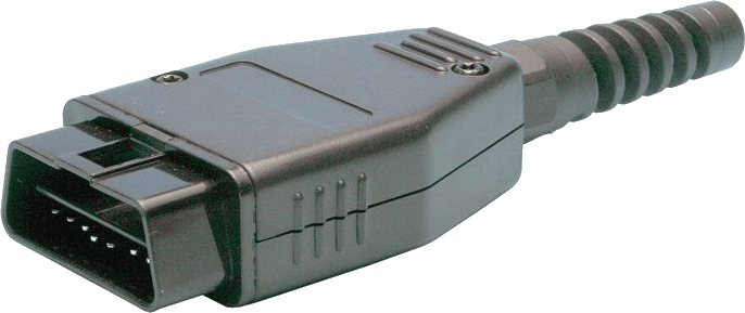
OBD2 Connector: I highly recommend getting an OBD2 connector. It should be mandatory. You can plug the dupont wires directly into the OBD2 port. It’s not recommended, but it can be done if you can’t find a connector. Not having an OBD2 connector will make the process really tedious. I mean it.
DC-DC Buck Converter: If you want to power the board using the 12V car battery instead of the USB interface, you will need one of these. They convert 12V to a lower voltage that can be used by the ESP32.
Most DC-DC Buck Converters are not automotive grade. There is a high chance of them burning out and ruining your ESP32. Automotive voltage is dirty and can spike quite a lot when the car starts or stops.
I recommend powering the board using the USB interface on the ESP32 and a car charger. Wiring the 12V directly can be tricky and may damage components if done incorrectly, so I won’t cover that here.
How to wire the components?
Before we even get started, I want to really emphasize that the pins you choose on the board aren’t all that important. The CAN protocol is called TWAI on an ESP32 board; TWAI works with any pin. You can change the pins you use in the code.
But there are some pins you should avoid https://randomnerdtutorials.com/esp32-pinout-reference-gpios/
Even though the strapping pins are marked as usable, do not mess with them. Especially GPIO2. These pins are made to sit at a certain voltage, and changing the voltage will make the board enter download mode. You won’t be able to upload any sketches (code).
I personally used GPIO4 and GPIO5, which worked best for me. Using GPIO2 and GPIO15 would’ve worked really well but I knew I couldn’t use them.
GPIO5 might be a strapping pin, but if the voltage is high, it acts as expected.
For the Arduino Uno, do not waste your mental resources and just follow the diagram I provided.
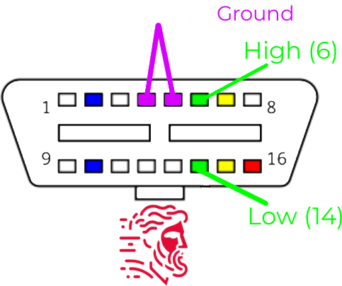
OBD2 Layout
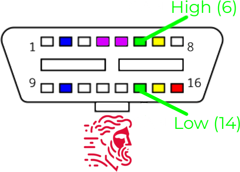
The pins you want to be looking at are pins 14 and 6 which are CAN Low and CAN High respectively. Marked with green.
ESP32 Wiring
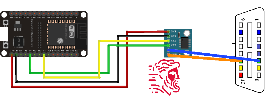
As you can see, it’s really simple.If you bought an ESP32 board and a CAN transceiver with the header pins soldered on, you can wire them up using Dupont wires. It’s really easy.
Then solder CAN High and CAN Low to pins 6 and 14, respectively, and you’re done.
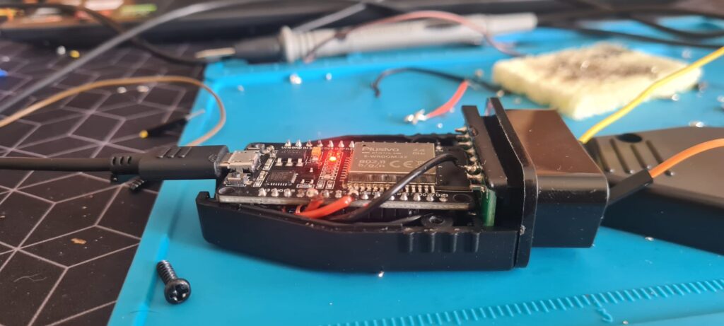
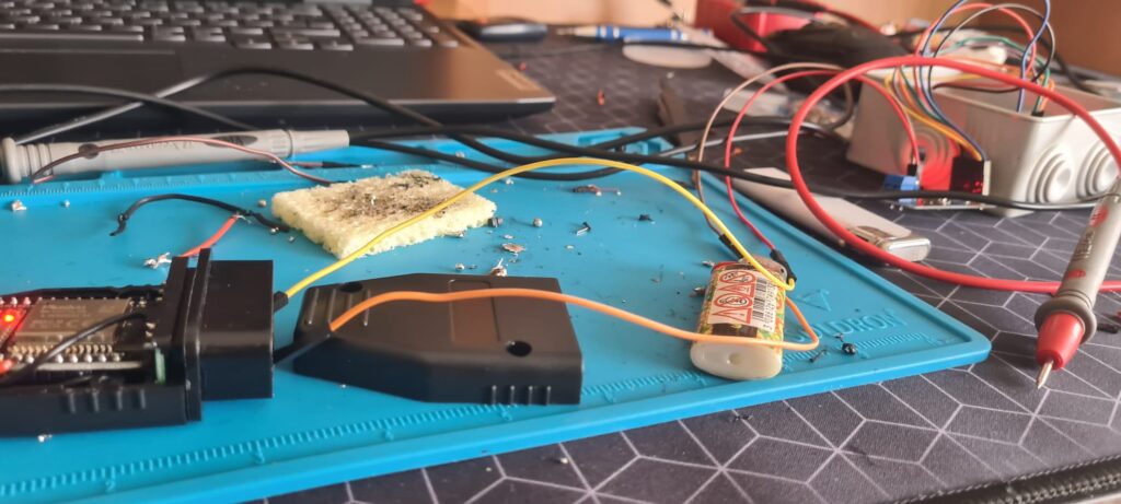
Although if you really solder everything together with short wires, you can get it to fit inside of an OBD2 adapter like I did:
Arduino Uno Wiring
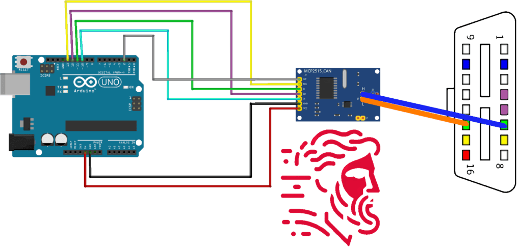
It might seem a bit more complicated, but you have absolutely no soldering to do. The MCP2515 board only comes in this version; plug everything in as per the diagram and you should be good to go.
You should end up with something like this:
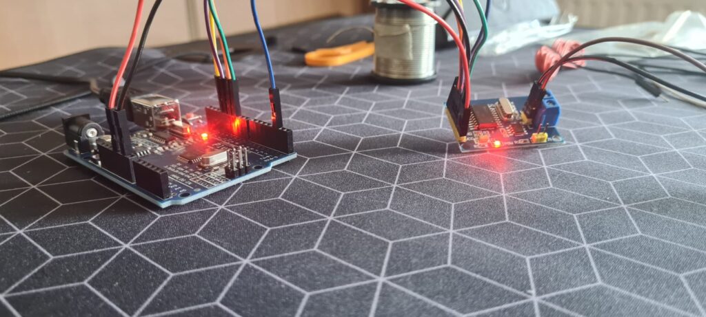
Which you can eventually put into a small enclosure.
Initial Testing Software
We will be using the Arduino IDE, so all you have to do is download it from https://www.arduino.cc/en/software
I’ll be working on Linux and will help the Linux folks with the issues I ran into.
After you’ve downloaded the IDE, make sure to run the following command if you’re on Linux:
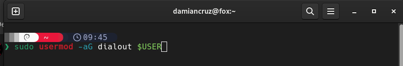
sudo usermod -aG dialout $USERThis makes it so that you have permissions to read and write to the USB interface. If not you’re going to get a permission error in the Arduino IDE.
ESP32 Dependencies
After you’ve done so, there is a really great tutorial on installing the ESP32 dependencies here:
https://docs.sunfounder.com/projects/umsk/en/latest/03_esp32/esp32_start/03_install_esp32.html
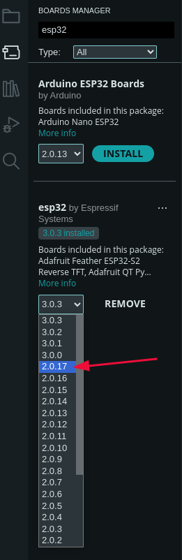
To start out, I’d recommend you get the ESP32 version 2.0.17 since the new versions don’t work with the simple CAN library. We will use that version to test our boards before connecting them to the car.
You can also keep the latest ESP32 version but edit the code depending on your preference.
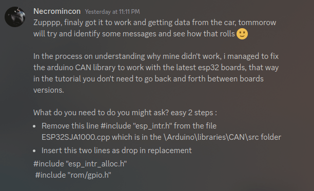
If you get the newer version, you will see an error as such:
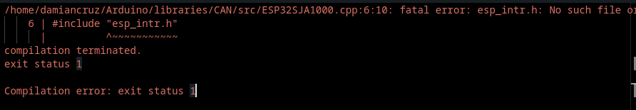
Which can be fixed in code so you can use it with the latest library ( You can thank Necromincon from my Discord)
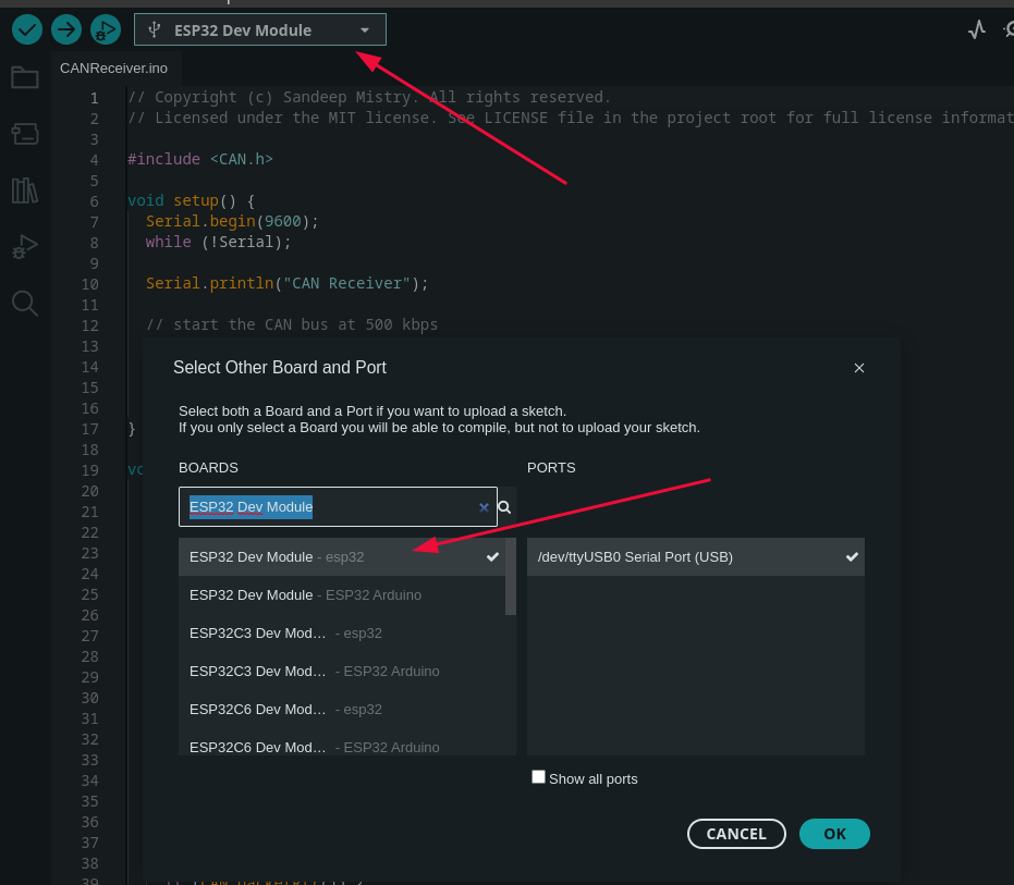
In the top part you should see the board selector; your device might get automatically recognized as an ESP32 if not:
Click on it, click on your board, and in the search box, search for “ESP32 Dev Module”
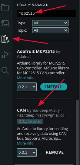
Once you’ve done so, we need to get the CAN library by Sandeep Mistry.
In the boards manager, search for “mcp2515” and scroll for a bit until you see “CAN by Sandeep Mistry” and install it.
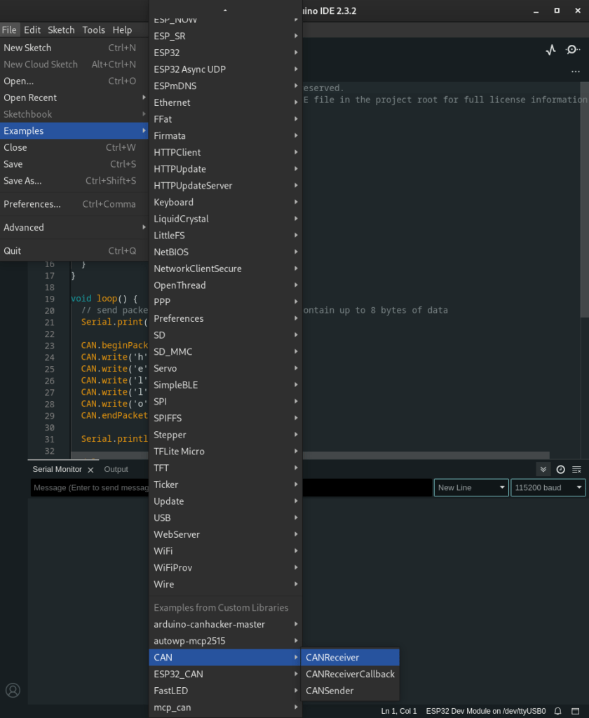
Now go to File -> Examples -> CAN -> CANSender
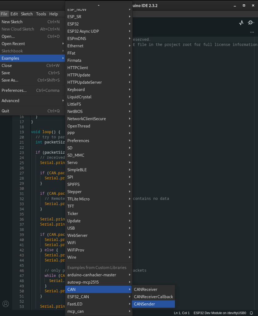
A new sketch should open:
- Press the upload button
- Click on the serial monitor and select the baud rate of 9600
- On the physical board, press the button labeled “EN” (Enable).
- You should see messages on the serial monitor coming from your ESP32
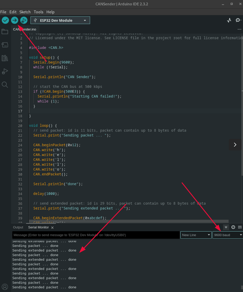
Now your board is set up to send the message “hello world” over the CAN bus.
Arduino Uno
For your Arduino Uno, the process is similar, but with an added step. You don’t have to install any dependencies. Just make sure to select your board as an Arduino Uno.

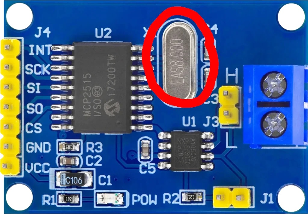
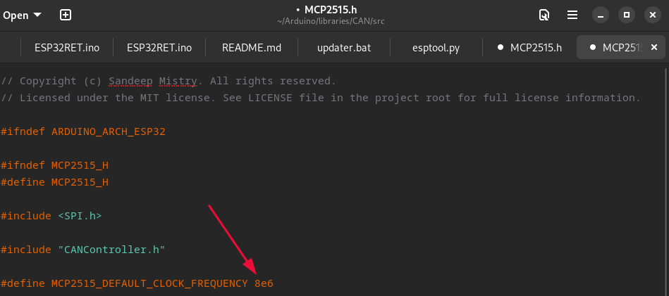
Now go to the CAN library installation folder and look for the header file MCP2515.h
It should be under ~Arduino/libraries/CAN/src on Linux.

Now look at your MCP2515 board. You’ll most likely see that your crystal is at 8mhz, if so change the clock frequency from 16 to 8 in the MCP2515.h file.
Go back to the Arduino IDE and choose the CAN example “CANReceiver” instead.
Building our own CAN Bus
Flash that to your Arduino Uno, and then connect your boards together. CAN High to CAN High and CAN Low to CAN Low.
Make sure to open the serial monitor on your Arduino Uno and select 9600 baud.
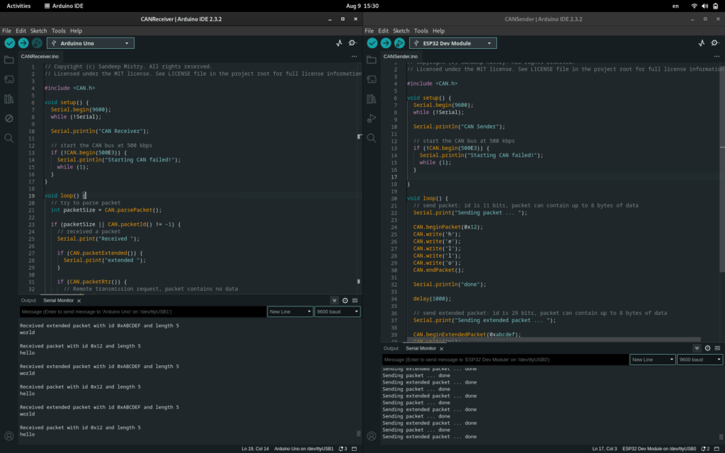
You should now have your own makeshift CAN bus. Isn’t that nice?
Common issues
If you’re not getting data or are seeing errors, you must diagnose the issue. Put on your engineering hat. Here are some troubleshooting steps for the ESP32:
- Make sure all your connections are secure and everything is soldered on right
- With your multimeter probe on a ground pin see each pin on the CAN transceiver
- You should get 3.3V on VCC, 3.3V on TX and, should see voltage on CAN High/Low and RX, but those fluctuate.
- Swap around the CAN High and CAN Low pins.
- If you have repeating messages in the serial monitor, your RX and TX pins might be shorted together.
- If you have a sudden drop in communications, CAN High and CAN Low might be shorted together.
- Swap the RX and TX pins by adding the following to the ESP32 sketch in the “void setup()” function.
- CAN.setPins(rxPin, txPin);
If you still can’t figure it out, come to my Discord and I’ll personally help you: Our Discord community.
Installing ESP32RET
If everything went well and you’re sure none of the pins are shorted out.
Congratulations.
Your device should now be safe to use on a real car. (emphasis on “should”)
Now we’re ready to move on and use the ESP32RET code. Which will allow us to integrate our device wirelessly and to use SavvyCAN.
I’ve made a fork of the original code that makes it cleaner for our purposes and removes the LED and Bluetooth functionality since we don’t need it.
EDIT: I decided to keep the Bluetooth functionality since you can integrate it as an ELM327. You can do that and then use it as a Bluetooth mobile diagnostics tool, albeit not a good one.
I also added a stoic quote to the serial log because you need it.
If you use the original code, you’ll get some errors in the terminal and will need to install the FastLED library.
The original was made to work with a specific ESP32 board project sold by collin80 The EVTV ESP32 CANDue. But we can use the code with a normal ESP32 just as well.
Steps
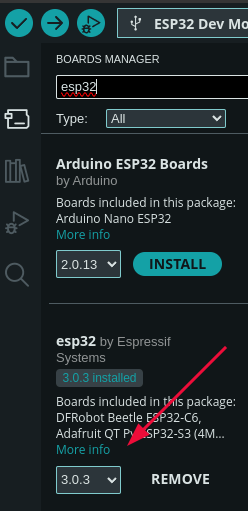
In the boards manager make sure you get the latest ESP32 dependencies.
Go into the Arduino libraries folder (on Linux it is under ~/Arduino/libraries)
cd ~/Arduino/librariesAnd then clone the following repositories:
git clone https://github.com/logosred/ESP32RET
git clone https://github.com/collin80/can_common.git
git clone https://github.com/collin80/esp32_can.git
cd esp32_can
git checkout 66d1440c9e53ccaeaccb6bfa91bde89cf7e368e6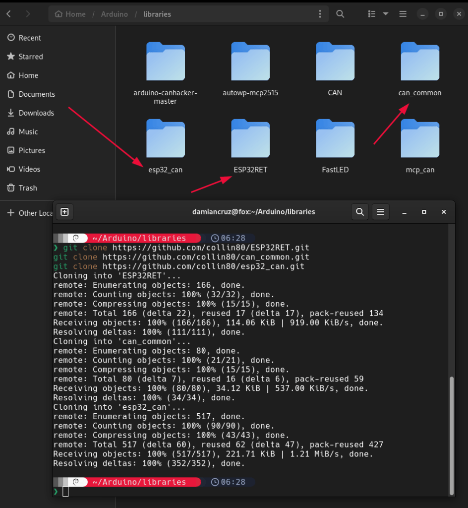
Make sure the name of each folder stays the same.
Now, in the Arduino IDE, click on File -> Open and select the ESP32RET.ino file.
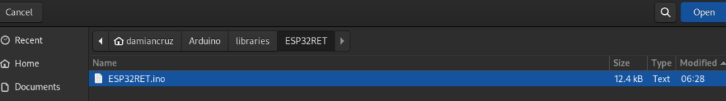
A lot of things will open up; don’t worry, you don’t have to mess with any of it.
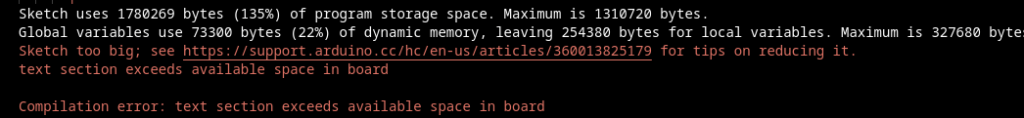
Go to Tools -> Partition Scheme and select “Minimal SPIFFS”
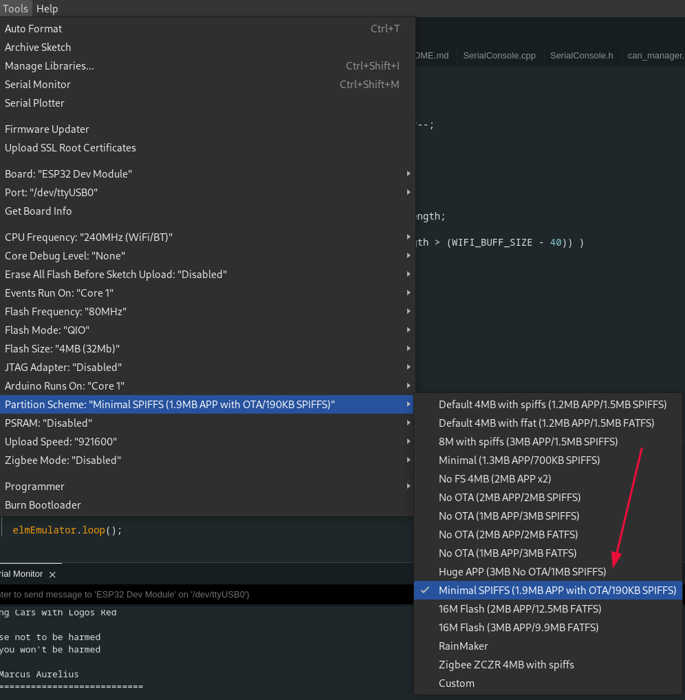
If you don’t, you’ll get an error like the following:
Click on upload in the upper left corner, and your sketch will upload.
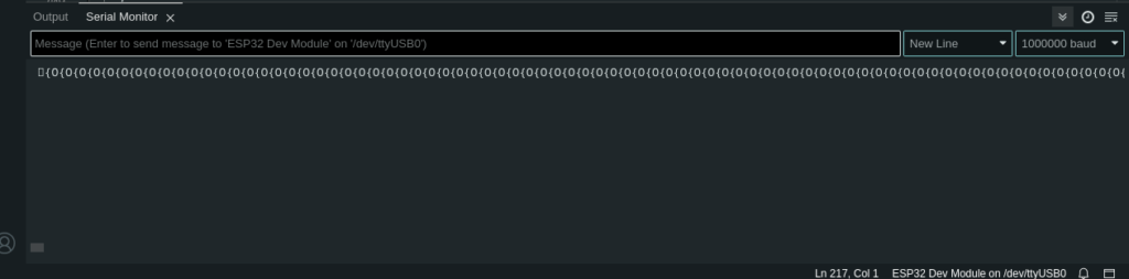
Open up the serial monitor, set the baud rate to 1,000,000, and then press the EN button on your ESP32.
You should see the following:
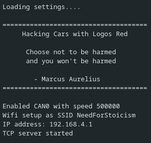
Now you’re hacking cars with Logos Red.
You are almost done.
There are some occasions when it bugs out. Seems to be a bug within the Arduino IDE. If so, make sure that the serial monitor isn’t turned on when you plug in your board.
- With your serial monitor off plug in your ESP32.
- Plug in your ESP32
- Turn on the serial monitor
- Press the EN button
Connecting to SavvyCAN
If you don’t have SavvyCAN:Here is a post from me detailing how to compile it from source on Linux.
- A new Wi-Fi network “NeedForStoicism” or “A0RET-SSID” should be available. Connect to it.
- The password for it is “by.virtue.defended” for my repository and “aBigSecret” for the original repository.
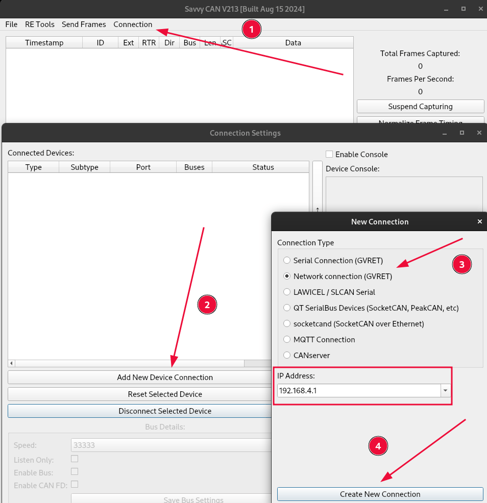
- Open up SavvyCAN and click on Connection -> Open Connection Window.
- Click on “Add New Device Connection.”
- Select “Network connection (GVRET)”
- It should automatically fill out the IP address as 192.168.4.1
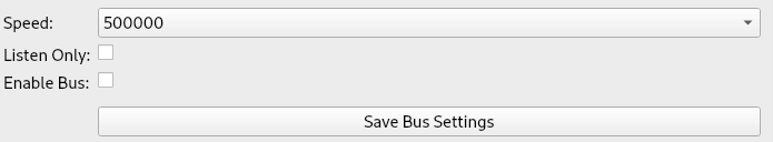
Down below, put the speed to 500000 (not necessary, but a precaution).
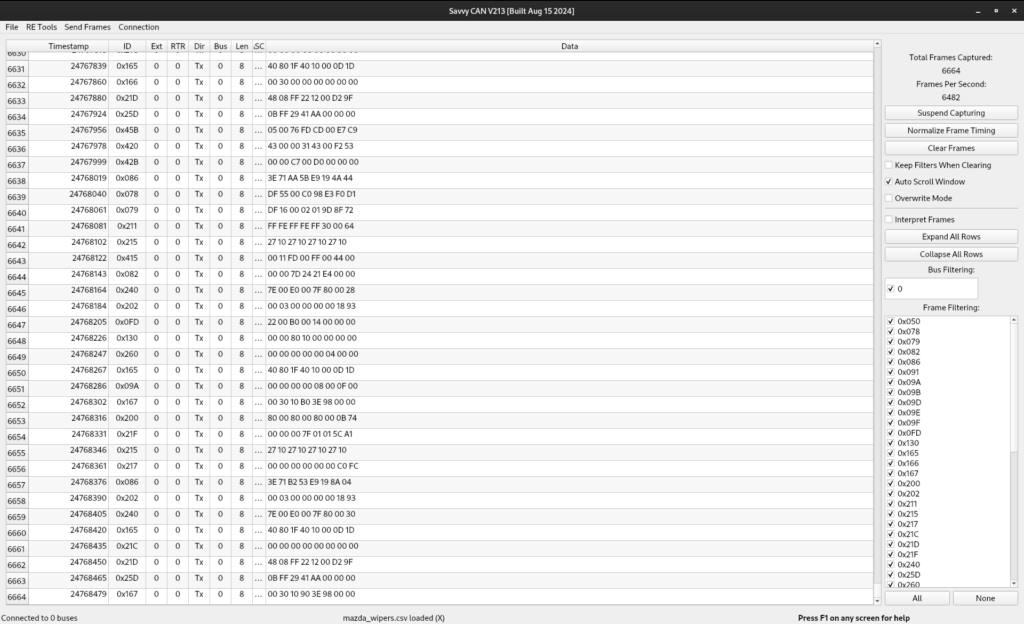
As soon as you plug the ESP32 into your car, you should see data flying out, as follows:
Now hopefully you’re familiar with SavvyCAN from my virtual car hacking post. If not, here it is so you can understand the basics:
How To Hack a Virtual Car: Working with Kali SavvyCAN ICSim
I really recommend that you first try sending commands to a virtual car before testing on your real car.
What next?
The best way to have fun is to do a replay attack. Perform an action, record it with SavvyCAN, then send it back to the CAN bus.
The CAN bus is fault-tolerant, so you most likely won’t cause permanent damage. A simple unplugging of your battery should revert the fault codes if you cause any.
I am not responsible for any damage you cause to your car, but I would be glad to help you fix it.
Once you’re confident in your abilities, you can start sending commands to your car. The CAN bus is really complex and fun to work on. It has more features than you’d initially believe, such as interacting with an ECU, reading fault codes, dumping firmware, etc.
You can use the UDS (Unified Diagnostic Service) tool in SavvyCAN (Under “Send Frames”) in order to interact with the main ECU.
https://en.wikipedia.org/wiki/Unified_Diagnostic_Services These are the common service identifiers and what they achieve.
Conclusion
In conclusion, by following this guide, you’ve successfully built a car hacking device designed to send remote commands to a vehicle. Using an ESP32, SN65HVD230 CAN transceiver, and Arduino Uno, you’ve learned how to wire the components with tools like a soldering iron, multimeter, and Dupont wires.
We walked through installing and configuring essential software, including the Arduino IDE, ESP32RET firmware, and SavvyCAN, enabling you to interact with the car’s CAN bus over Wi-Fi. This hands-on project has equipped you with the skills to remotely control various car functions, from basic commands to more advanced car hacking techniques.
I thank you for reading and I trust this guide has proved useful to you.
More Resources
If you didn’t understand something or you need some help, we have our own Discord community and I currently offer free coaching.
You can also leave us some feedback with what you did not understand and we will make sure to correct it.